


Reference: NETXTE5898
Brand: XTENDLAN
Reference: 115760111
Brand: Avast Software s.r.o.
Reference: NASSYN1166
Brand: SYNOLOGY
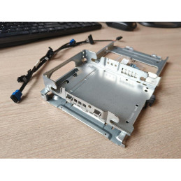
Reference: PCD4189
Brand: DELL
Reference: 65327
Banner


Business terms and conditions

Delivery policy

Return policy
Your message was successfully sent.
There was a problem with sending your message, please contact us via contact page.
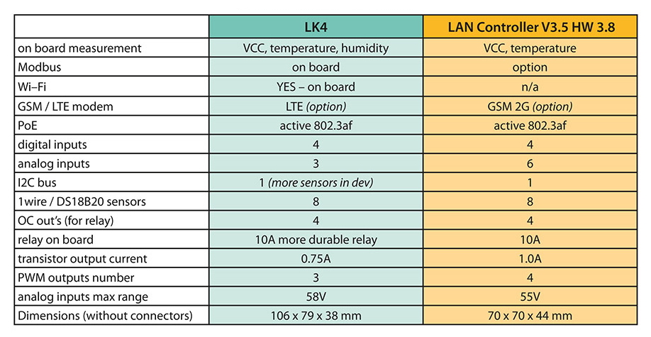
Tinycontrol LAN driver v4.0
LAN controller with relay is a simple, versatile and affordable device for controlling outputs based on information from various sensors. It serves as a web server that displays various types of sensors and allows remote control of outputs.
In addition, it is possible to program events and corresponding actions to meet conditions on any of the sensors. A scheduler that allows the device to be turned on/off at a certain time or for a certain period of time can be suitable for many applications. There are 3 PWM outputs for controlling lighting or an electric motor.
The new LAN controller v4.0 integrates all the previous IoT experiences into one universal device. It represents a smooth continuation of the previous series, now in a more practical form.
Dual communication interfaces:
You can use a wired Ethernet connection, a wireless Wi-Fi connection (802.11n), or both at the same time. There is also a variant with LTE connectivity. The LAN controller can be fully configured from a web page available on the built-in web server. It is also possible to send arbitrary commands to the device via HTTP (bypassing the web page) or MQTT (after configuring the connection).
Comparison of versions 3.8 (3.9) and 4.0:
Usage examples:
Hardware:
Software:
BASIC SPECIFICATIONS
Supply voltage: 8-58V
Power consumption: 0.5 W
PoE: yes, 802.3af, mode A passive with jumper
Interface: Ethernet 10/100Mbps, Wi-Fi (802.11n)
Relay: 10A, 250VAC
Operating temperature: –20 to +85 °C
Dimensions: 106 × 79 × 38 mm
Weight: 130g
The LAN controller is supplied with a DIN rail installation box without a power supply.
Power supply is possible in two ways - with a classic jack power supply or a PoE injector .
For usage examples and more information, see Technical Support .
The manufacturer provides an MQTT cloud service for status display and control via the Internet. Thanks to this service , outputs can be switched or controlled without routing settings.o monitor the status of the LAN controller in the local network, but the operation of the service cannot be guaranteed. In case of using the MQTT service, you can also use the mobile application . It is available for Android devices and allows you to control the outputs and monitor the status and values of the inputs simply via your phone .
.png)
Overview of currently supported sensors and devices
Analog inputs
Logic inputs (digital)
1Wire bus
I2C bus
Serial port
Modbus RTU
Modbus TCP
HTTP client
Data sheet
Your review appreciation cannot be sent
Report comment
Report sent
Your report cannot be sent
Write your review
Review sent
Your review cannot be sent
Our pricing is always guided by the principles of a fair price. We do not artificially move prices or brag about inflated percentages. You can always find price history for each product.
check_circle
check_circle
Are you shopping without registering? You pay more and miss out on important benefits. Registered customers at daycomp.eu receive sales disc ...
Agartha Company s.r.o., operator of the daycomp wholesale e-shop, hereby informs its customers about the opening hours during the Christmas ...
We have recently introduced a modernized method of electronic delivery of selected consumer licenses to our offer, which brings faster and m ...